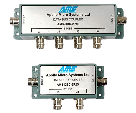
A data bus coupler is a device used to connect one bus to another without causing any interruption. It functions as a breaker that couples and extends the bus while allowing for bus monitoring. The stub connection is established using a coupling transformer and two fault isolation resistors. The coupler consists of bus-in and bus-out connections, along with at least one stub connection.
The primary purpose of the coupler is to reduce signal reflections and maintain proper signal impedance levels. Fault isolation resistors within the coupler provide protection to the main bus in the event of a short circuit occurring in the stub. All devices, including the bus controller, bus monitor, and remote terminal, must be connected to the stub ends of the coupler.
Basic Characteristics: | - - - |
---|---|
Case: | CRCA Steel with Tin Plating conforming to IS : 513: 2008 |
Coupler Module: |
Encapsulated with the following Components Coupler transformer conforming to MIL-T-21038 Fault Protection resistor conforming to MIL-R-39007 |
Transformer Turns Ratio: | 1:1.41±3% (Compliant to MIL-T-21038) |
Input Impedance: | 3000Ω Minimum (75KHz to 1MHz) |
Pulse Width: | 2µ Sec |
Rise/Fall Time: | 150nS. Maximum |
Droop: | 20% maximum (250KHz) |
Overshooting And Ringing: | ±1V peak (250KHz square wave with 100ns Maximum Rise and Fall Time) |
Common Mode Rejection: | >45dB at 1.0MHz |
Fault Protection: | Resistors in series with each Bus winding |
Termination: | 78Ω ±2%, 1W |
Insulation Resistance: | >1000MΩ at 250 VDC between Conductors |
Dielectric Strength: | 600 Vrms between Cable Shield and Bus, Stub and Shield |
Operating Temperature: | -55°C to +125°C |
Storage Temperature: | -55°C to +130°C |
Stub Voltage: | 1.0V to 14.0V p-p (line-line, signal voltage) |
Connector Type: | BJ 77 (Jack type with socket contact Bayonet coupled-3 lug) conforming to MIL-C-49142 |